USB-C Breakout and 3.3V Regulator Building Block Board
USB-C Breakout and 3.3V Regulator Building Block Board#
Today I sent the first of my new building block boards to JLCPCB for fabrication and assembly.
Originally, I was going to create two separate boards: a USB-C breakout board and a 3.3V regulator board. After thinking about it for a while, though, I realised that most of my future projects are likely to need both. If I am bringing USB-C power into a board, there is a good chance I will also want a local 3.3V rail.
So instead of making two separate boards, I merged both functions into a single small PCB.
The board measures 35 mm by 22 mm and includes a USB-C port, a 3.3V regulator, and a few basic protection features. The goal is not to create an indestructible industrial power supply, but to make something more robust and convenient than simply dropping a regulator onto a bit of protoboard.
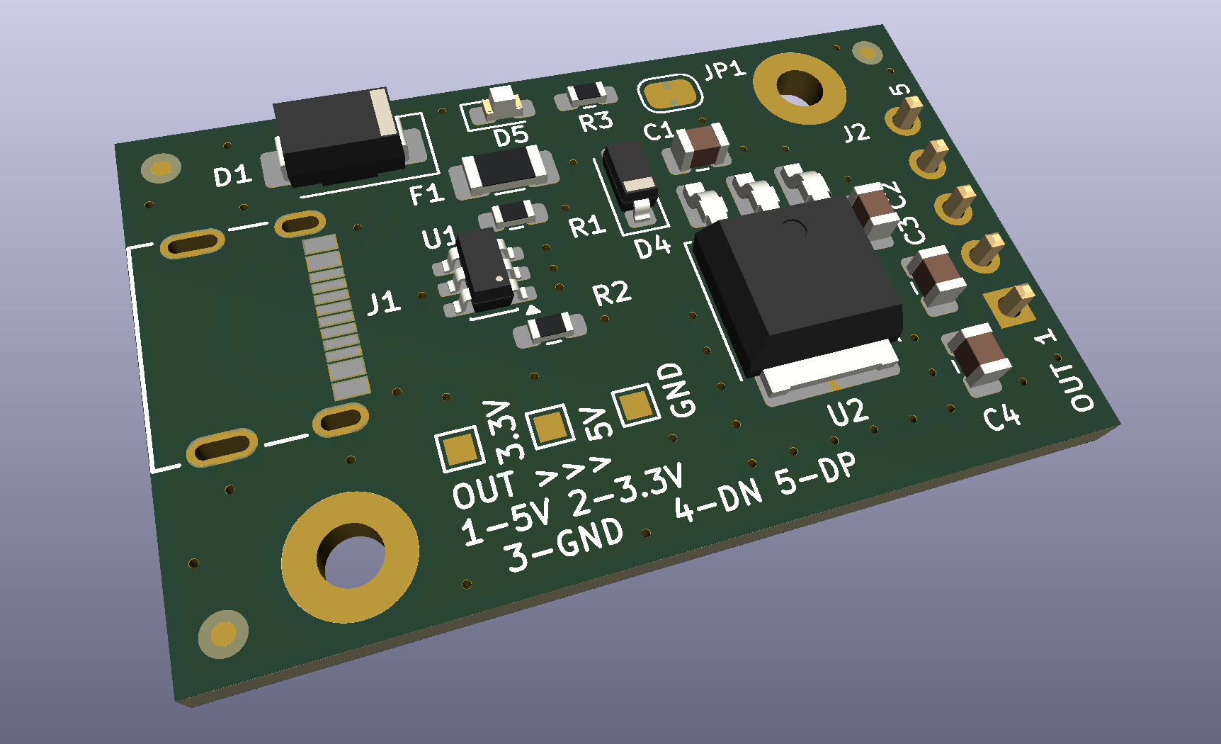
3D render of the USB-C breakout and 3.3V regulator building block board
The 3D render gives a better sense of the board’s overall layout. Despite the small footprint, it still accommodates the USB-C connector, protection circuitry, AP2114 regulator, and a simple 2.54 mm breakout header carrying 5V, 3.3V, GND, D−, and D+.
The board includes the following components:
- 2 × 5.1 kΩ 0603 resistors connected to CC1 and CC2, allowing the board to request 5V from USB-C power sources.
- 1 × USBLC6-2SC6 for ESD protection on the USB data lines.
- 1 × SMAJ5.0A TVS diode on VBUS to help protect against voltage transients.
- 1 × 500 mA hold / 1 A trip PPTC resettable fuse.
- 1 × MBR130LSFT1G Schottky diode to help prevent voltage being back-fed into the USB-C VBUS line.
- 1 × AP2114D-3.3TRG1 3.3V regulator.
The PCB is a four-layer board.
The top layer is used mainly for components, routing, and local ground fill. The second layer is a solid ground plane. The third layer is used mainly for power distribution, and the bottom layer carries signals including the USB D+ and D− lines from the USB-C connector.
The USB data lines are passed directly to optional 2.54 mm header pins, along with 5V from the USB-C input, the regulated 3.3V rail, and ground. This means the board can be used either as a simple USB-C power input module or as part of a larger prototype where the D+ and D− lines are passed on to something like a CH340, FTDI, or other USB interface device.
I also added a pair of M2 mounting holes for those times when a temporary-permanent solution is required. We have all been there.
I approached this board with manufacture in mind from the start rather than designing it purely for hand assembly. That affected the component choices. I moved toward 0805 and 0603 parts, which are still possible to inspect and rework manually if needed, rather than going straight to 0402 parts, which are much less forgiving on the bench.
I also included a simple solder jumper for the power LED. That way, the LED can be disconnected if it is not required, or if I need to minimise the power budget for a particular prototype.
Assuming the board works as expected, it should become a useful little bench prototype module for future projects. It also gives me a practical way to validate the component choices before reusing them in larger designs.
That is really the point of these building block boards. They are small enough to be cheap, simple enough to test properly, and reusable enough to become part of a larger development workflow.
If this one behaves itself, it will likely become the standard USB-C power entry block for several of my future boards.
If you are looking for reusable open hardware modules to speed up your bench testing, or need support designing custom breakout circuits, check out our catalog at Protoworks (NI).
- 2026-10-17 Refining the Protoworks service offerings Lab
- 2026-09-27 Belfast Tech Week Lab
- 2026-09-19 Refining the UCMOD Architecture R&D
- 2026-09-06 Giving AI Agents a Way to Talk to Protoworks Software
- 2026-09-03 A Morning at a Manufacturing Trade Show Lab
- 2026-09-01 Debugging 921600 Baud on the ATtiny1614 R&D