Some Integration Testing
Some Integration Testing#
Today I decided to do some integration testing between my first three building block boards.
Sometimes just hooking things together and seeing how they react is the best way to find unexpected behaviour. Individual board testing is useful, but integration testing is where the small assumptions and wiring mistakes tend to show up.
With that in mind, I connected the following boards and parts:
- 1 x USB-C Power Input & 3.3 V Regulator Board
- 2 x RS485 Non-Isolated Breakout Boards
- 1 x Digital IO Expander Board
- 2 x Raspberry Pi Pico 2W boards
- 1 x EC11 Rotary Encoder on a prototype PCB
- 20 m Cat 6 cable
The boards were arranged as a transmitter and receiver setup.
The receiver side consisted of a Raspberry Pi Pico 2W and an RS485 Breakout Board, powered by USB from a laptop.
The transmitter side consisted of another Raspberry Pi Pico 2W, an RS485 Breakout Board, and the Digital IO Expander Board, powered by the USB-C Power Input & 3.3 V Regulator Board.
The two RS485 boards were connected using a 20 m Cat 6 cable, and the EC11 Rotary Encoder was connected to the Digital IO Expander Board on the transmitter side.
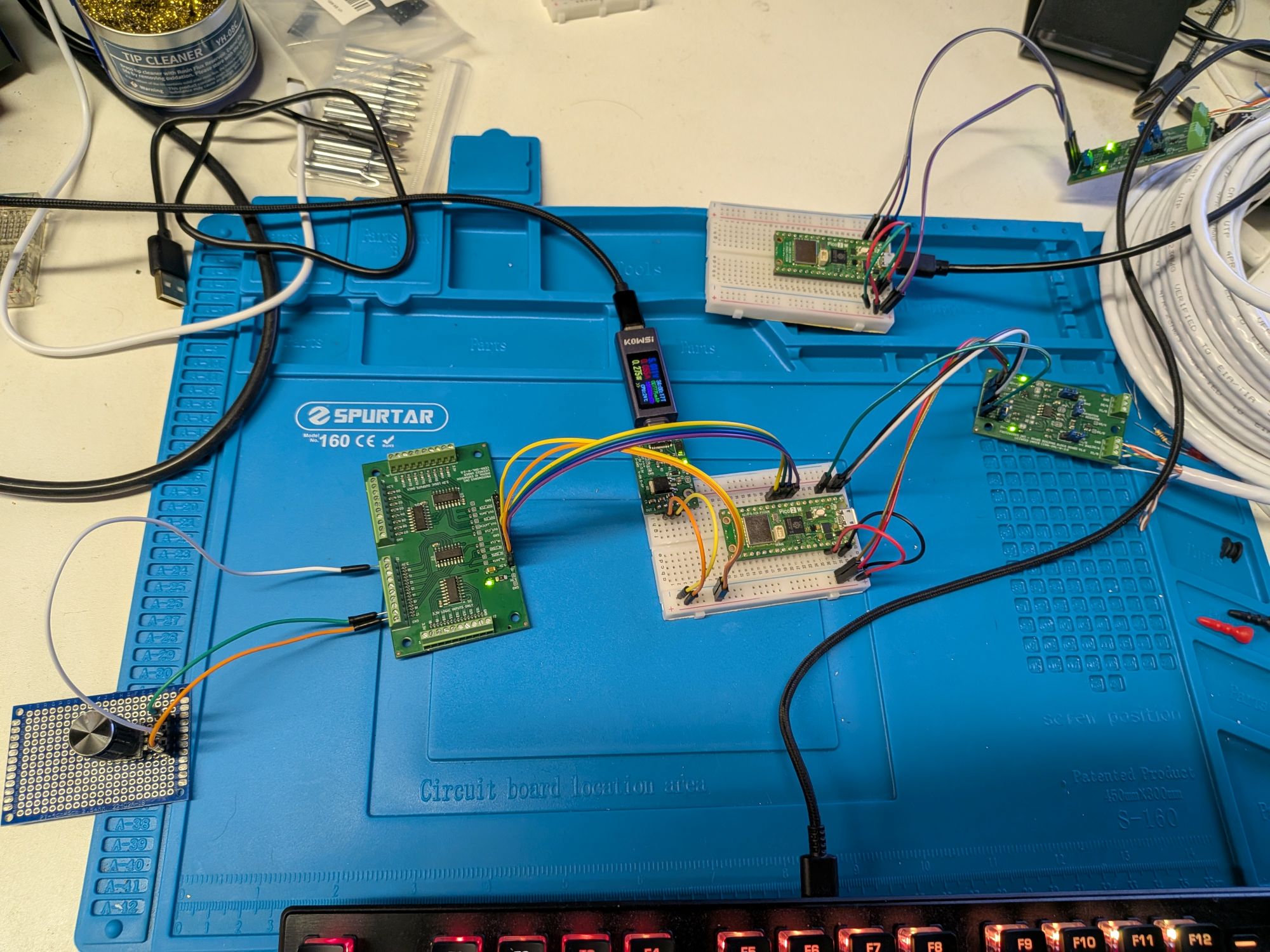
Integration Test Setup
The plan was simple: rotate the EC11 Rotary Encoder on the transmitter board and see if the receiver board could pick up the signal over RS485 and print the result to the serial terminal.
RS485 Link Test#
Before combining everything, I first checked the RS485 communications by rerunning the same test code from yesterday.
This time I decided to increase the baud rate and see how the boards performed. I tested the link at:
- 2,000,000 baud
- 4,000,000 baud
- 6,000,000 baud
I will not repeat the code here, as it was covered in yesterday’s entry, but the results were quite surprising.
For a short bench test over this particular 20 m cable setup, the link worked up to 6,000,000 baud without issue, with the messages coming through correctly.
I suspect that adding more boards to the bus would still be possible, although it would likely need more careful tuning, especially around bus loading, termination, cable layout, and software buffering. I am also aware that microcontroller UART FIFO buffers are not exactly overflowing with spare capacity, so sustained high-speed traffic would need to be handled carefully.
For this test, though, the objective was to check the RS485 boards themselves, and they appear to be solid.
Combining RS485 and Digital IO#
The next step was to combine the RS485 test with the Digital IO Expander test code.
I had already created a script for reading the digital inputs on the expander board. The next job was to transmit the scanned input values from the transmitter board to the receiver board over the RS485 link.
The transmitter code would only send an update when the current scanned value from the Digital IO Expander differed from the previous scanned value. This keeps the traffic low and avoids continuously sending the same state when nothing has changed.
A Small Power Supply Mistake#
I had a slight diversion while doing a verification step before connecting the EC11 rotary encoder.
When I activated one of the digital inputs using a jumper wire from a 3.3 V terminal, I was getting an intermittent signal when the Digital IO Expander was powered from the Raspberry Pi Pico.
However, when the transmitter board was powered from the USB-C Regulator Board, the signal was reliable.
At first, this puzzled me.
I started checking the usual suspects:
- Was there sag on the 3.3 V rail?
- Were the capacitors insufficient?
- Was the bulk capacitor on the input too small?
- Were the pull-down resistors wrong?
- Was the input signal noisy?
It turned out to be simpler than that.
When powering the Digital IO Expander from the Raspberry Pi Pico, I had accidentally powered it from the Pico’s VBUS pin rather than the dedicated 3V3(OUT) pin. That meant the Digital IO Expander was being powered at 5 V instead of the intended 3.3 V.
The 74HC165 input shift registers can operate from a range of supply voltages, but the input thresholds scale with the supply voltage. Typical 74HC parts are usually intended for operation up to around 6 V, depending on the exact manufacturer and part variant.
When the device is powered from 5 V, a 3.3 V input signal can become marginal because the input-high threshold is also higher.
So the 3.3 V input was just close enough to work some of the time, but not comfortably enough to be reliable.
The fix was easy: power the Digital IO Expander from the Pico’s 3V3(OUT) pin instead of VBUS.
After that, the signal was rock solid.
A little embarrassing, but also exactly the kind of issue integration testing is supposed to catch.
Rotary Encoder Test#
The next step was to get the EC11 rotary encoder working with the Digital IO Expander.
Wiring up A, B, and C/common was straightforward, and rotating the knob appears to be sending input changes through the expander board correctly.
At this stage, I have not yet added the proper quadrature decoding logic. The current test is mainly about confirming that the input changes can be read by the Digital IO Expander and then passed over the RS485 link.
Next Steps#
The next step is to write the decoding logic for the EC11 rotary encoder and integrate it into the transmitter board code.
I also intend to attach a small OLED screen to the receiver board. The idea is to display a value that increases or decreases depending on the direction of rotation, while also echoing the state of the digital inputs.
That should make a useful end-to-end demo:
- Rotary encoder input on the transmitter side
- Digital IO Expander scanning
- RS485 transmission over 20 m Cat 6 cable
- Receiver-side decoding
- OLED display output
For now, I am happy with the progress.
The individual boards have already been tested, but this was the first step towards proving that they can work together as a practical system.
If you are looking for reusable open hardware modules to speed up your bench testing, or need support designing custom breakout circuits, check out our catalog at Protoworks (NI).
- 2026-10-17 Refining the Protoworks service offerings Lab
- 2026-09-27 Belfast Tech Week Lab
- 2026-09-19 Refining the UCMOD Architecture R&D
- 2026-09-06 Giving AI Agents a Way to Talk to Protoworks Software
- 2026-09-03 A Morning at a Manufacturing Trade Show Lab
- 2026-09-01 Debugging 921600 Baud on the ATtiny1614 R&D