Designing a Modular ATtiny Microcontroller Board
Today I started designing a microcontroller module as part of a larger project that I have been working on.
The first version is based on the Microchip ATtiny1614. The board should also be compatible with the ATtiny1624 and ATtiny3224 in their equivalent 14-pin packages, although there are naturally some differences in the peripherals and capabilities provided by each device.
The module connects to its carrier board through a simple 20-pin, 2 × 10, 0.1-inch socket. This plugs into a corresponding 2 × 10 pin header on the carrier board.
The first carrier board I am developing is based on my Isolated RS485 Building Block Board. Rather than having a fixed microcontroller integrated into the design, the carrier version will accept one of these removable microcontroller modules.
My current plan is to create at least two versions of the module:
- An ATtiny-based version
- An STM32-based version
Other versions may follow later.
The main idea is to define a reasonably microcontroller-agnostic connector layout. When a microcontroller supports a particular peripheral, that peripheral will be routed to the same position on the connector regardless of which module is installed.
For example, I²C, SPI and UART will appear on consistent connector pins across the different module designs. The physical microcontroller pins used internally may change, but the carrier board will see the same external interface.
This should make it possible to select a microcontroller according to the requirements of a project without having to redesign the entire carrier board.
The main electrical requirement is that each module must operate at 3.3 V, or include whatever circuitry is necessary to make it compatible with a 3.3 V system.
I have deliberately avoided adding input protection or power protection circuitry to the microcontroller module. I want to keep its responsibilities limited to hosting the microcontroller and the supporting components it requires. Protection, power conditioning and application-specific circuitry will instead be handled by the carrier board.
A render of the current ATtiny1614-based microcontroller module is shown below:
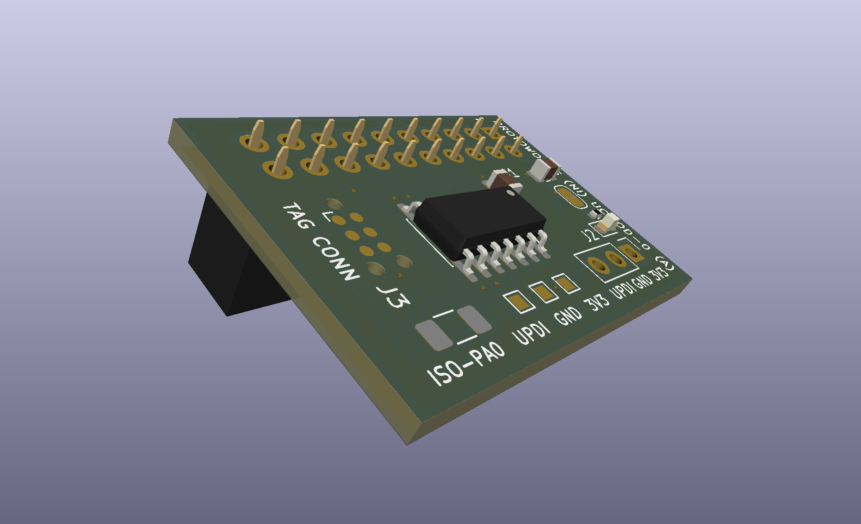
ATtiny1614 microcontroller module board
The current connector layout exposes I²C, SPI and UART, along with analogue and general-purpose digital I/O.
Several of the pins are multiplexed. When a particular peripheral is not required, its pins can instead be used as analogue inputs or general-purpose digital I/O. This allows the limited number of pins available on the ATtiny1614 to be used as efficiently as possible.
Programming is handled separately from the 20-pin carrier connector. The board includes several possible in-circuit programming connections, including pogo-pin pads, conventional header pads and a Tag-Connect footprint.
Keeping programming off the main connector avoids using valuable carrier pins for a function that is normally only needed during development or servicing.
The design is still at an early stage, but the overall connector layout is beginning to take shape. The next step will be to review the ATtiny board, finalise the common connector definition and begin developing the matching carrier board.
Once that interface has been established, I can start designing the STM32 version around the same connector layout and see how successfully the abstraction works across two quite different microcontroller families.
- 2026-10-17 Refining the Protoworks service offerings Lab
- 2026-09-27 Belfast Tech Week Lab
- 2026-09-19 Refining the UCMOD Architecture R&D
- 2026-09-06 Giving AI Agents a Way to Talk to Protoworks Software
- 2026-09-03 A Morning at a Manufacturing Trade Show Lab
- 2026-09-01 Debugging 921600 Baud on the ATtiny1614 R&D