Expanding the Building Block Ecosystem
Today I sent the following Building Block Boards off to the fab for manufacture:
- Rev A of the UCMOD-0 Microcontroller Module, an ATtiny1614-based plug-in module that can be fitted to compatible Building Block Boards to provide them with processing capability.
- Rev C of the Isolated RS485 Building Block Board, which includes the revised input protection circuit as well as support for the new UCMOD interface.
I actually skipped manufacturing Rev B of the Isolated RS485 board. That revision had already been designed, but before sending it to manufacture I decided to add the UCMOD header and its associated circuitry, so the design moved directly on to Rev C.
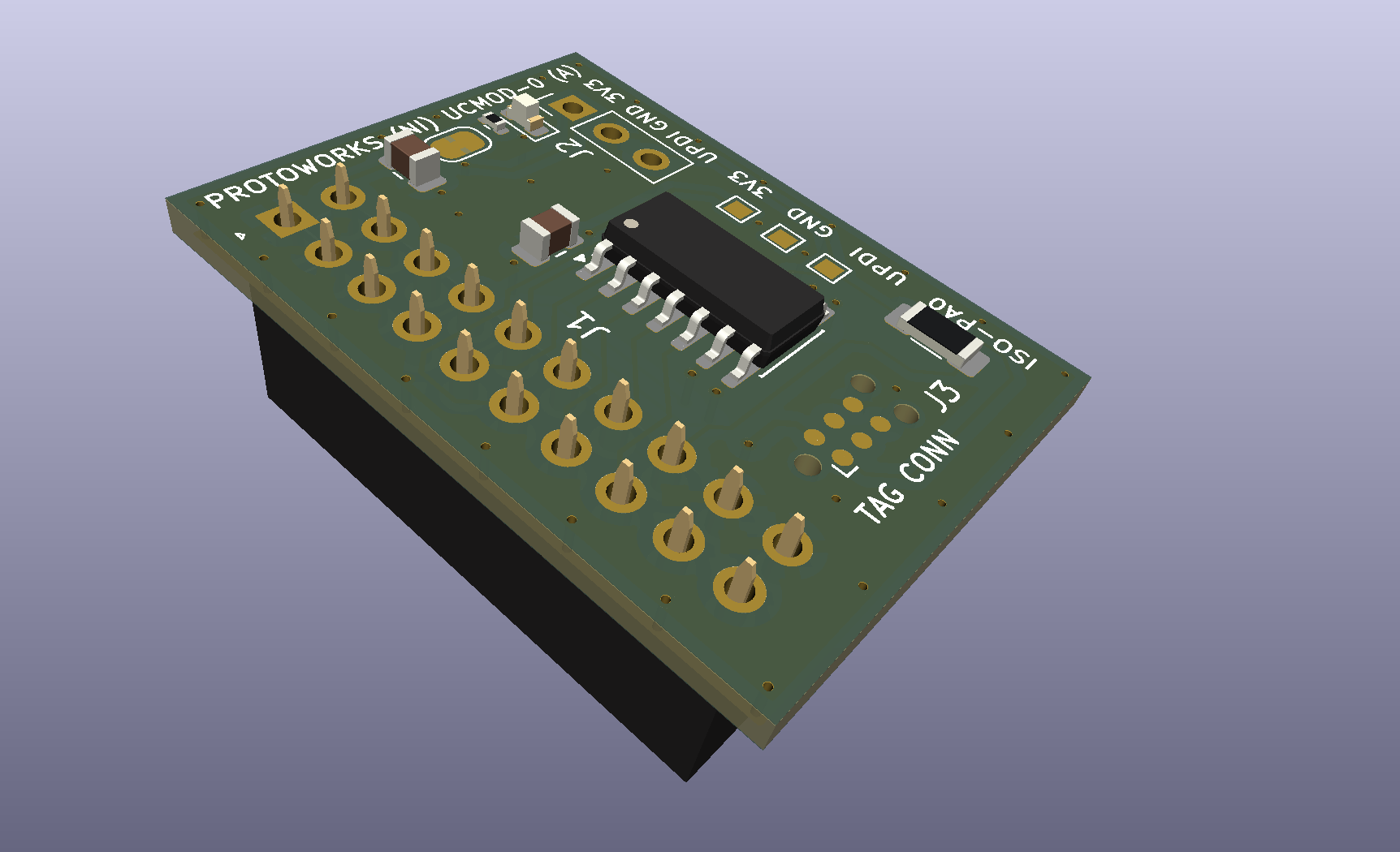
ATtiny1614 microcontroller module board (UCMOD-0)
The UCMOD-0 Microcontroller Module is a small plug-in board that connects to a 2x10 0.1-inch header on a carrier board. In this case, the first carrier is the Rev C Isolated RS485 Building Block Board.
The important part of the design isn’t really the ATtiny1614 itself, but the interface between the microcontroller module and the carrier board.
The 2x10 connector is intended to provide a standard interface between the two, allowing the microcontroller to be upgraded or changed in the future without having to redesign the carrier board. A relatively simple ATtiny module might be sufficient for one application, while another could use an STM32 or ESP32 module while retaining the same carrier hardware.
Currently, the connector pinout is defined as follows:
| Pin | Function | Pin | Function |
|---|---|---|---|
| 1 | GND | 2 | 3V3 |
| 3 | GND | 4 | RESERVED |
| 5 | I2C_SCL / GPIO0 | 6 | I2C_SDA / GPIO1 |
| 7 | UART_TX / GPIO2 | 8 | UART_RX / GPIO3 |
| 9 | SPI_MOSI / GPIO4 | 10 | SPI_MISO / GPIO5 |
| 11 | SPI_SCK / GPIO6 | 12 | SPI_CS / GPIO7 |
| 13 | AN0 / VREF / GPIO8 | 14 | AN1 / DAC / GPIO9 |
| 15 | AN2 / GPIO10 | 16 | AN3 / UPDI / GPIO11 |
| 17 | RESERVED | 18 | GND |
| 19 | 3V3 | 20 | GND |
Where a microcontroller supports a particular interface, such as I2C, SPI or UART, that peripheral will be assigned to the corresponding pins on the connector.
Pins that aren’t required for those functions can instead be used as general-purpose digital I/O, or as analogue inputs where supported by the microcontroller. Firmware will, of course, need to target the appropriate microcontroller pins that have been mapped onto the UCMOD connector.
The plan is to produce a range of UCMOD-compatible microcontroller modules, initially including STM32G0 and ESP32-C6 versions, which can then be plugged into a corresponding range of carrier boards.
This should make it possible to mix and match the amount of processing power, memory and peripheral capability required for a particular project without redesigning the rest of the hardware.
I’ll be documenting the design process for those boards here in the near future. This is my first attempt at defining a standard microcontroller module interface, so I’m expecting it to evolve as I build more boards around it.
The ATtiny1614 is intended to sit at the simpler end of the range. It isn’t the most powerful microcontroller, but it is still a very capable little device and should be more than adequate for a large number of control and interface applications.
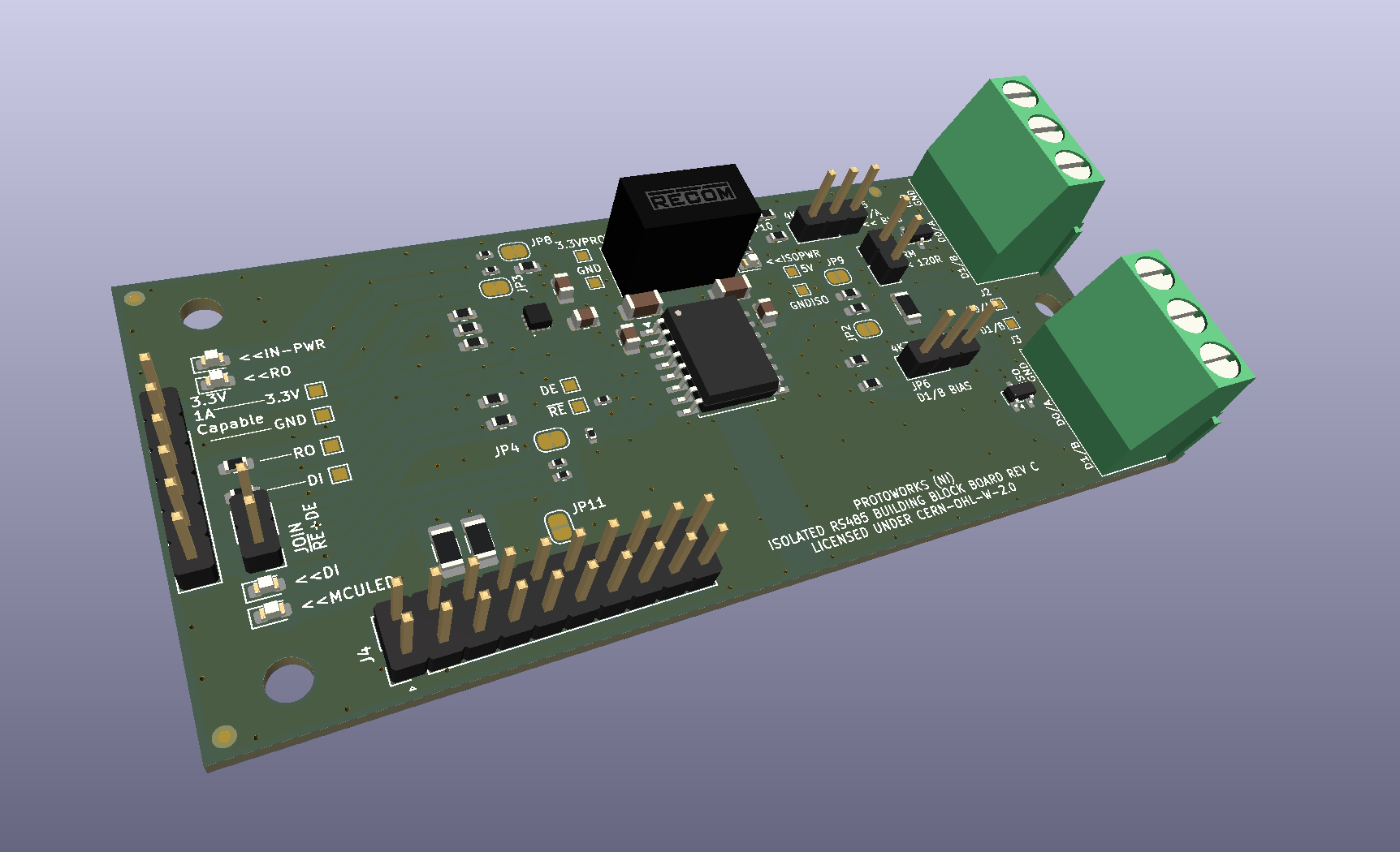
Rev C Isolated RS485 Building Block Board
I also sent off Rev C of the Isolated RS485 Building Block Board.
This revision now uses a TI TPS259474LRPWR eFuse for input protection, providing reverse-current protection, improved input-voltage protection and configurable over-current protection.
It should make the board considerably more robust than the previous versions. If the supply voltage moves outside the configured operating range, or the load exceeds the configured current limit, the eFuse disconnects the protected side of the circuit.
I’ve also upgraded the isolated DC-to-DC converter to the B0305S-1WR3, which offers improved efficiency as well as better stock availability than the previous part.
The TPS259474LRPWR monitors the input voltage using a resistor network connected to its UVLO and OVLO pins, while the over-current trip threshold is configured to approximately 1 A using a 3.3 kΩ resistor connected to the ILM pin.
The voltage-monitoring network uses three resistors: 360 kΩ, 39 kΩ and 200 kΩ.
Together, these configure the TPS259474L to disconnect the output if the input voltage falls below approximately 2.7 V, preventing the circuit from attempting to operate from an unstable supply. Power is restored once the input rises to approximately 3.0 V.
At the other end of the operating range, the eFuse disconnects the output if the input rises to around 3.6 V and reconnects once it has fallen back to approximately 3.3 V.
This creates a protected operating window around the nominal 3.3 V supply. The exact switching points will vary slightly because of resistor tolerances and the tolerances within the eFuse itself, but it should provide a substantially better protection mechanism than the previous design.
+3.3 V IN
   |
 [360 kΩ]
   |
   +---- EN/UVLO
   |
 [39 kΩ]
   |
   +---- OVLO
   |
 [200 kΩ]
   |
  GND
I also changed the terminal blocks compared with the previous version of the board.
Rev C uses larger 5 mm-pitch screw terminal blocks, allowing larger wire gauges to be accommodated and generally making field wiring easier. The smaller connectors used on the previous version also proved to be a bit of a pain to use, so hopefully this will be a much better solution.
I’m looking forward to getting the boards back and seeing how everything fits together. Hopefully there won’t be any last-minute issues to iron out.
More importantly, though, it feels like I’m starting to build up a small ecosystem of useful boards that can be combined in different ways for different projects, rather than each new PCB being an entirely standalone design.
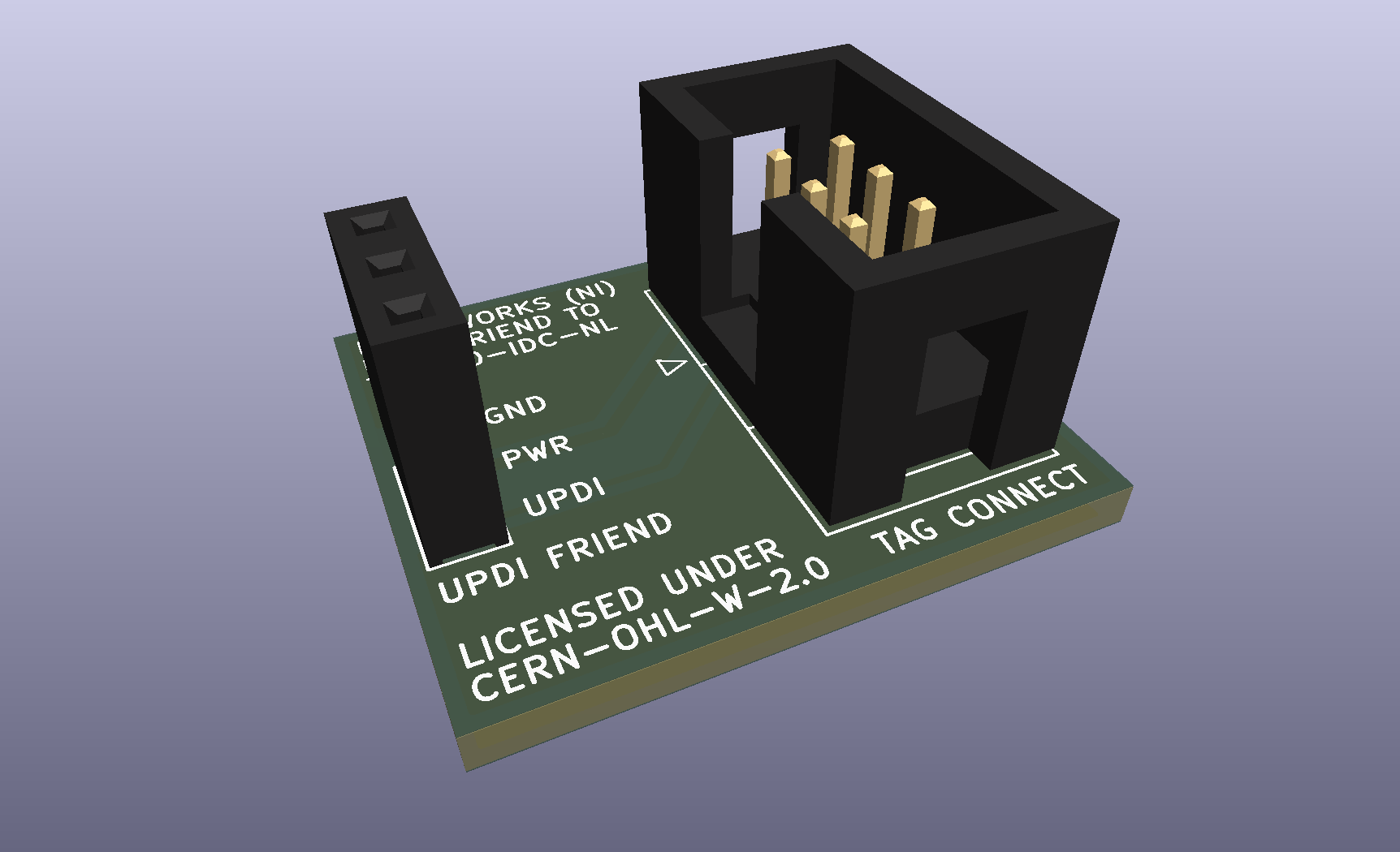
UPDI Friend to Tag Connect Board
I’ve also developed a simple breakout board that will allow me to connect a UPDI Friend to a 6-pin IDC-based Tag-Connect TC2030 cable.
This will give me a convenient way of programming the UCMOD-0 and other UPDI-based boards without having to fit a permanent programming connector to every PCB.
It’s a very simple board, and the few required components can easily be ordered separately, so there isn’t much reason to have it assembled by the PCB manufacturer. I’ll make the design available once I’ve had the PCB manufactured and confirmed that everything works as expected.
On another note, I’ll be attending Manufacturing Solutions Northern Ireland on the 3rd of September at the La Mon Hotel and Country Club, and the Northern Ireland Manufacturing & Supply Chain Conference & Exhibition on the 10th of September at the Eikon Exhibition Centre in Lisburn.
If you’re going to either event, drop me an email and let me know. It would be great to meet up there.
- 2026-10-17 Refining the Protoworks service offerings Lab
- 2026-09-27 Belfast Tech Week Lab
- 2026-09-19 Refining the UCMOD Architecture R&D
- 2026-09-06 Giving AI Agents a Way to Talk to Protoworks Software
- 2026-09-03 A Morning at a Manufacturing Trade Show Lab
- 2026-09-01 Debugging 921600 Baud on the ATtiny1614 R&D