RS485 Breakout with 48V Passthrough Building Block Board
RS485 Breakout with 48V Passthrough Building Block Board#
The next building block board I’ve been working on is an RS485 breakout board based around the MaxLinear SP3485EN.
The SP3485EN is a 3.3V RS485 transceiver with a similar role and pinout to the MAX3485E. That makes it useful for this kind of small prototyping board, where I may want to try alternative parts later.
The reason for building this board is simple: microcontroller GPIO is fine on a PCB, and sometimes acceptable over a short jumper wire, but it is not designed for reliable signalling over any real distance. Once signals need to leave the board and travel across a machine, a workshop, a building, or a larger installation, something more robust is needed.
That is where RS485 comes in.
RS485 is a differential signalling standard commonly used in industrial and automation systems. Instead of sending a signal as a single voltage relative to ground, it sends the signal as a voltage difference between two wires, usually labelled A and B. This makes it much more tolerant of noise and voltage differences than a simple single-ended GPIO signal.
For my use case, the aim is not to create a fully isolated industrial RS485 interface, at least not in this first version. This board is intended as a practical building block: something I can plug into future microcontroller projects when I want a simple RS485 link, screw terminal access, optional RJ45 cabling, and optional 48V passthrough for distributed power.
It may come in handy for testing a few concepts for my digital sequencer project, and possibly for the next version of my weather station if that ends up being mounted at the top of a flag pole or in some other equally inconvenient location.
What This Board Is For#
This board is intended to sit between a 3.3V microcontroller and an RS485 bus.
On the microcontroller side it exposes the basic logic-level signals:
- RO — receiver output
- DI — driver input
- DE — driver enable
- /RE — receiver enable
- 3.3V
- GND
On the bus side it provides screw terminal connections for the RS485 A/B pair, along with optional 48V passthrough. The 48V is not used by the SP3485EN itself; it is simply routed through the board so that the same cable or connector arrangement can carry both data and power to another board.
That last part is important: this is not Power over Ethernet. Although the board has an optionally populated RJ45 connector, I am only using it as a convenient multi-pin connector for RS485 and optional power distribution. It should not be plugged into normal Ethernet equipment.
The intended features of the board are as follows:
A simple jumper that links the independent /RE and DE input lines together. When fitted, this allows a single microcontroller GPIO to control the transmit/receive direction of the transceiver.
A jumper-selectable 120 ohm termination resistor across the RS485 A/B pair. This can be enabled when the board is at the end of a cable run, or left disconnected when the board is in the middle of the bus.
Jumper-selectable bus biasing, allowing either stronger 1K bias resistors or weaker 4K7 bias resistors to define the idle state of the RS485 bus.
Basic protection on the 48V passthrough input, including a fuse, TVS diode, and P-channel MOSFET reverse-polarity protection. This is intended to provide some protection when passing 48V through to the screw terminal output and optional RJ45 connector.
I did consider using a PPTC resettable fuse instead of an SMD fuse. For this board, though, I decided that a conventional fuse was probably the more predictable option, especially at this voltage. It also keeps the failure mode fairly obvious: if something goes badly wrong, the fuse opens and needs to be replaced.
That is inconvenient, but on a cheap building block board I would rather have a small part sacrifice itself than risk passing a fault further downstream into something more expensive.
Termination and Biasing#
One of the things I wanted this board to support was configurable termination and biasing.
The 120 ohm termination resistor is there to match the characteristic impedance of the twisted pair cable and reduce reflections on longer cable runs. It should normally only be enabled at the ends of the RS485 bus, not on every node. If every board on the bus had termination permanently fitted, the effective resistance across the bus would quickly become too low and the transceivers would have to drive a much heavier load.
The biasing resistors are slightly different. Their job is to define the idle state of the bus when no device is actively transmitting. Without biasing, the A/B pair can float, and the receiver may interpret noise as valid data.
For this board I added jumper-selectable biasing so I can experiment with stronger 1K resistors or weaker 4K7 resistors. The correct choice depends on the bus length, number of nodes, termination, cable type, and what other devices on the bus are already doing. In a real system, biasing should normally be applied in one place on the bus rather than blindly enabled on every node.
The RJ45 Jack#
The optional RJ45 jack I’ve selected is the Amphenol FCI 54602-908LF, an 8-position horizontal RJ45 connector.
This is not an Ethernet jack in the full networking sense. It does not include Ethernet magnetics, and it is not shielded. For this board, that is intentional. I am not trying to create an Ethernet interface, and I am not trying to pass Ethernet through the connector. The RJ45 connector is simply being used as a convenient, cheap, and widely available multi-pin connector for RS485 and optional 48V passthrough.
That distinction matters.
A normal Ethernet port usually has magnetics between the cable and the PHY. Those magnetics provide galvanic isolation and are part of the electrical design of Ethernet. This board does not have that. The SP3485EN connects to the RS485 pair through the protection and termination/biasing parts on the board, not through Ethernet magnetics.
Because the connector is unshielded, any cable shield, if present, is not connected to the board through the jack. For a small building block board intended for prototyping, that keeps things simple. For a harsher industrial environment, a shielded connector, proper chassis bonding, surge protection, and possibly galvanic isolation would all be worth considering.
I have also included a 1206 resistor footprint next to the RJ45 jack. This can optionally be populated with a 0 ohm link if I decide to route the 48V passthrough onto pins 4 and 5 of the RJ45 connector.
By default, that link can be left unpopulated, which means the RJ45 connector does not automatically carry 48V. I like this arrangement because it makes the higher-voltage connection an intentional configuration choice rather than something that happens just because the connector is fitted.
Not Ethernet, Not PoE#
Because this board uses an RJ45 connector and can optionally carry 48V, it would be easy to mistake it for some kind of Power over Ethernet device.
It is not.
There is no Ethernet PHY, no Ethernet magnetics, no PoE negotiation, and it does not follow normal PoE wiring or detection behaviour. The 48V passthrough is simply a direct power-routing option for my own RS485 cabling scheme.
That means this board should not be connected to normal Ethernet equipment. If I use the RJ45 option, the cable and connected boards need to be treated as part of a custom RS485/power system, not as network hardware.
Protection on the 48V Passthrough#
The 48V passthrough side of the board is intentionally separate from the RS485 transceiver. The SP3485EN only uses the 3.3V supply from the microcontroller side; the 48V rail is simply routed through the board for use by downstream hardware.
Even so, I wanted some basic protection on that passthrough path. The current design includes a fuse, a TVS diode, and P-channel MOSFET reverse-polarity protection. This is not a complete industrial protection scheme, but it should make the board a little more forgiving during bench testing and early prototypes.
The fuse is there to open if the board or downstream wiring suffers a significant fault. The TVS diode is there to clamp voltage spikes, and the P-channel MOSFET is there to reduce the chance of damage if the 48V input is connected with the wrong polarity.
As with the rest of this board, the protection is a compromise. A more serious version could add isolation, better surge protection, common-mode filtering, shield bonding, and more careful connector keying. For this version, I mainly wanted a practical board that was simple enough to build, inexpensive enough to risk during experiments, and useful enough to keep in the parts drawer.
What This Board Is Not#
It is worth being clear about the limits of this first version.
This is not a fully isolated industrial RS485 interface. It does not include isolated power, digital isolation between the microcontroller and transceiver, common-mode chokes, shield bonding, or a more comprehensive surge protection network.
That does not make the board any less useful. It just means it belongs in the category of practical prototyping tool rather than certified industrial interface. For bench testing, short-to-medium cable experiments, and early project bring-up, that is exactly the kind of board I wanted.
Board Layout#
The finished board layout is deliberately simple. The goal is not to create the final word in industrial RS485 interfaces, but to create a useful board that I can keep reusing while testing different embedded projects.
The screw terminals are placed along the edges of the board to keep wiring straightforward, while the SP3485EN and supporting termination/biasing parts sit close to the RS485 side of the circuit. The RJ45 connector is optional, so the board can be assembled either as a simple screw-terminal RS485 breakout or as a cable-friendly version using the RJ45 footprint.
The 48V passthrough routing is kept separate from the 3.3V logic side as much as practical on a small board. This is not isolation, but it does help keep the purpose of each section of the board clear: low-voltage logic on one side, RS485 bus handling in the middle, and optional power passthrough where needed.
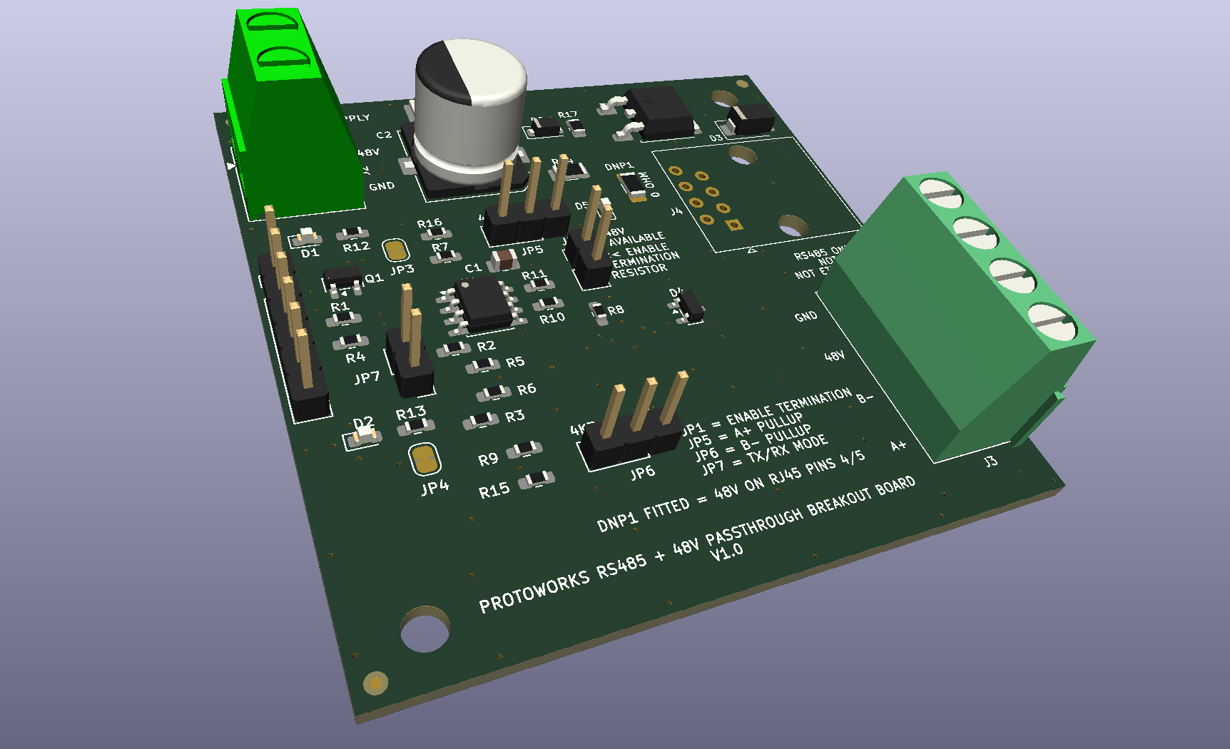
3D render of the RS485 Building Block Board
Closing Thoughts#
This board is not complicated, but that is partly the point.
It gives me a reusable RS485 building block with configurable termination, selectable biasing, screw terminal access, optional RJ45 cabling, and a protected 48V passthrough path. That should make it useful for early experiments with distributed embedded systems, especially projects where a microcontroller needs to talk beyond the edge of its own PCB.
For a future revision, I may look at a more industrial version with isolation, better surge protection, shield handling, and possibly a more deliberate connector scheme. For now, though, this version should be a useful addition to my growing collection of small prototyping boards.
If you are looking for reusable open hardware modules to speed up your bench testing, or need support designing custom breakout circuits, check out our catalog at Protoworks (NI).
- 2026-10-17 Refining the Protoworks service offerings Lab
- 2026-09-27 Belfast Tech Week Lab
- 2026-09-19 Refining the UCMOD Architecture R&D
- 2026-09-06 Giving AI Agents a Way to Talk to Protoworks Software
- 2026-09-03 A Morning at a Manufacturing Trade Show Lab
- 2026-09-01 Debugging 921600 Baud on the ATtiny1614 R&D