First Hardware Tests of the UCMOD-0 and RS485 Rev C
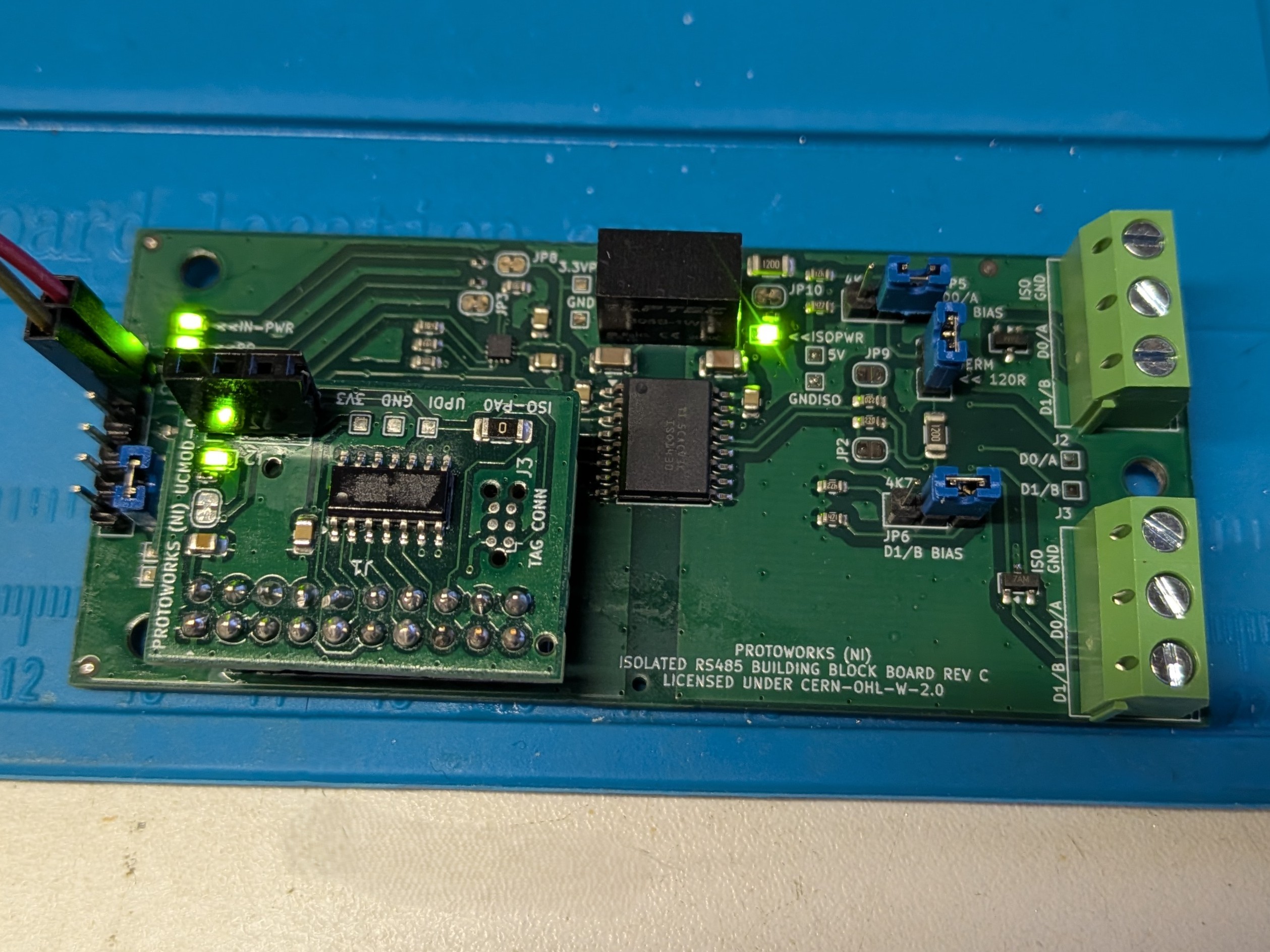
Today I received the latest revision of the Isolated RS485 Building Block Board and the first version of the ATtiny1614-based UCMOD-0 microcontroller module.
This was a particularly interesting batch because it gave me the opportunity to test not only the changes made to the RS485 board, but also the basic UCMOD concept in physical hardware for the first time.
RS485 Isolated Board Rev C#
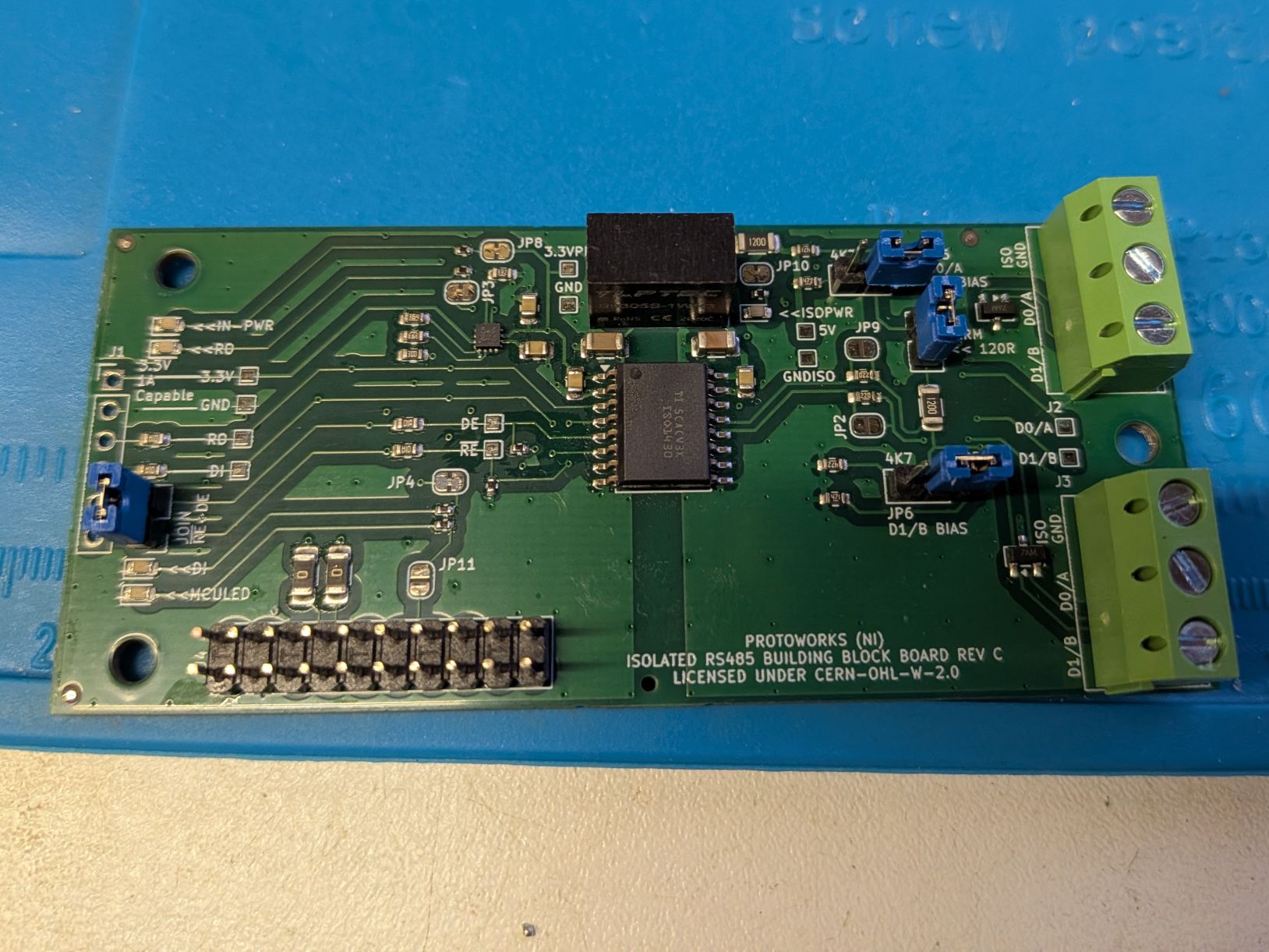
Rev C Isolated RS485 Building Block Board
Revision C of the Isolated RS485 board adds a UCMOD connector, an improved input protection circuit based around the TPS259474LRPWR eFuse, and a new DC-to-DC converter.
I started by soldering the header pins onto the board and carrying out my usual basic continuity checks to make sure there were no obvious shorts or broken connections.
I also checked the UCMOD header, which was pre-soldered during assembly, to make sure its pins were connected to the expected signals on the board.
No problems were found during these checks, which was reasonably reassuring given that the previous revision had already passed similar testing. The main structural change this time was the addition of the UCMOD interface, and everything appeared to have been laid out correctly.
The next step was testing the new under-voltage and over-voltage protection provided by the eFuse.
Using a bench power supply, I gradually reduced the input voltage from 3.3 V. At around 2.8 V, the under-voltage lockout (UVLO) activated and disconnected the output as expected. Increasing the supply again caused the output to reconnect at approximately 3.1 V.
I then tested the over-voltage protection by carefully increasing the input voltage. At around 3.6 V, the eFuse disconnected the output. Reducing the input again to a little above 3.3 V caused the output to reconnect.
In both cases, the eFuse behaved as expected.
I then moved on to checking the output of the new DC-to-DC converter.
With one of my USB-C Power Input & 3.3 V Regulator Boards supplying the input, I unfortunately didn’t record the exact output voltage, but from memory it was approximately 5.1–5.2 V, which is comfortably within the expected range.
I also wanted to see what happened near the upper end of the board’s permitted input voltage, so I increased the input to just below the point where the eFuse’s over-voltage protection activates.
At an input just under 3.6 V, the isolated supply increased to just under 5.5 V.
At this point the isolated supply was still within the TI ISO1430’s recommended VCC2 operating range of 3–5.5 V, although obviously towards its upper limit. The device has an absolute maximum VCC2 rating of 6 V, so this is a considerable improvement over the behaviour I observed with the previous version of the board.
The more important scenario for me isn’t really a supply voltage gradually drifting upwards, but someone accidentally connecting a 5 V supply to a board designed for 3.3 V.
In that situation, the eFuse should disconnect the input before the higher voltage reaches the rest of the circuit. The testing so far gives me much more confidence that the new protection circuit will handle that sort of wiring mistake appropriately.
I also tested the reverse-polarity protection.
As a deliberate reverse-polarity test, I applied approximately 15 V with the polarity reversed and the protection circuitry behaved as expected. This is around the limit of the negative input voltage that the TPS25947 family is specified to withstand, so I didn’t see much value in pushing the board any further.
More importantly, it’s far beyond anything this 3.3 V board should encounter during normal operation, and I’d still quite like to keep this particular board alive for the rest of the testing.
UCMOD-0 Board#
The UCMOD-0 is an ATtiny1614-based microcontroller module designed to plug into a standard 2x10 header on a compatible carrier board, in this case the Isolated RS485 board.
The connector provides a defined interface between the microcontroller module and the carrier board, allowing different microcontrollers to be used in the future without redesigning the carrier itself.
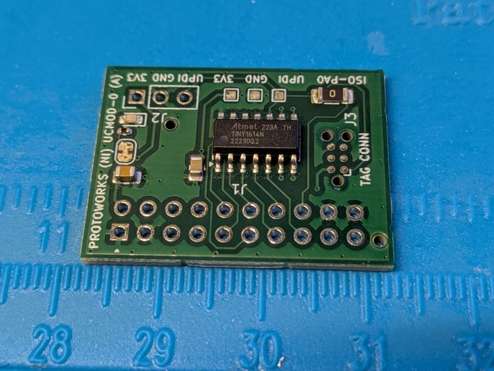
UCMOD-0 fresh from the fab
I soldered the two 2x10 connector onto the board along with the UPDI programming socket, which turned out to be slightly more challenging without glasses than I had anticipated.
Fortunately, everything still worked.
With the UCMOD-0 plugged into the RS485 carrier board, the module’s power LED illuminated when power was applied to the carrier.
I then carried out some basic continuity checks through the UCMOD interface.

UCMOD-0 combined with the RS485 carrier board and powered up
The UART TX and RX signals from the UCMOD connector were correctly connected through to the DI and RO pins of the TI ISO1430, and the 3.3 V and ground connections were also present where expected.
These are simple checks, but they’re an important milestone because this is the first physical test of the UCMOD interface itself.
At this stage I know that the module mechanically fits the carrier, receives power correctly and that the important communication signals are reaching the circuitry on the carrier board.
The next step is proving that those connections work electrically under software control.
Next Steps#
The carrier board has an LED connected to one of the GPIO pins exposed through the UCMOD connector, so the next test will be the traditional embedded “Hello World”: blinking an LED.
Once I’ve successfully programmed the ATtiny1614 and confirmed basic GPIO operation, I’ll move on to testing the UART connection between the UCMOD-0 and the ISO1430.
From there, the plan is to transmit some basic messages over RS485 to a second carrier board.
That board will initially either have a Raspberry Pi Pico 2 W connected to it or another UCMOD-0 module plugged into the UCMOD connector.
That should let me progress from individual electrical checks to a proper end-to-end test of the complete system:
UCMOD microcontroller → UART → isolated RS485 transceiver → RS485 bus → second carrier board.
If that works as expected, it will be a fairly significant validation of the UCMOD approach and the Building Block Board architecture around it.
Other News#
I’ll be attending a last-minute Maker meetup in Belfast tomorrow evening, which should be a good opportunity to meet some more people working on hardware and related projects locally.
I’ve also started work on an STM32G0-based UCMOD module, which should appear in a future post.
Beyond that, I’m considering a CH32V003-based version because of how inexpensive the microcontroller is, and possibly a GD32VF103-based module as well.
The longer-term idea is to have several compatible UCMOD modules available using different microcontroller families, allowing users to select the processor that best suits their application while continuing to use the same carrier boards and interfaces.
- 2026-10-17 Refining the Protoworks service offerings Lab
- 2026-09-27 Belfast Tech Week Lab
- 2026-09-19 Refining the UCMOD Architecture R&D
- 2026-09-06 Giving AI Agents a Way to Talk to Protoworks Software
- 2026-09-03 A Morning at a Manufacturing Trade Show Lab
- 2026-09-01 Debugging 921600 Baud on the ATtiny1614 R&D