Defining the Small and Large UCMOD Form Factors
Today was mostly an admin day: accounts, emails, taxes and all the fun stuff that comes with running a business. I could go on a rant, but that’s probably best avoided.
I did, however, manage to improve the Protoworks website slightly. I’ve added Slack integration so that anyone with questions about my products or projects can chat with me directly. I’ll trial it for a few weeks and see whether it improves the customer experience.
Likewise, if anyone has questions about any of the articles on this website, feel free to join the Protoworks Slack channel and ask away.
A Few More Additions to UCMOD-1#
I also managed to spend some time working on the UCMOD-1 STM32 “large” UCMOD board.
One addition is a simple optional four-pin header intended for a 1.3-inch OLED screen, using a GND, VCC, SCL/SCK, SDA arrangement. This matches many of the common 1.3-inch OLED modules available from places such as AliExpress, although it is worth noting that some smaller OLED modules use a different pin order, including arrangements where GND and VCC are swapped.
Naturally, there is nothing particularly OLED-specific about the connection electrically, so if an OLED isn’t fitted it can simply be used as another I²C connector.
I’ve also added a four-pin JST-SH connector for connecting SparkFun Qwiic modules. Again, this isn’t restricted to Qwiic devices and can be used with other suitable I²C devices.
There are also optional I²C pull-up resistors that can be connected using solder jumpers if required. Since an I²C bus only needs an appropriate set of pull-ups somewhere on the bus, this means the onboard resistors can be left disconnected when pull-ups are already provided elsewhere.
The board is starting to take shape and will probably be queued for production shortly. I’ll give it a few more days to make sure I haven’t missed anything obvious and to see whether anything else occurs to me before committing to manufacture.
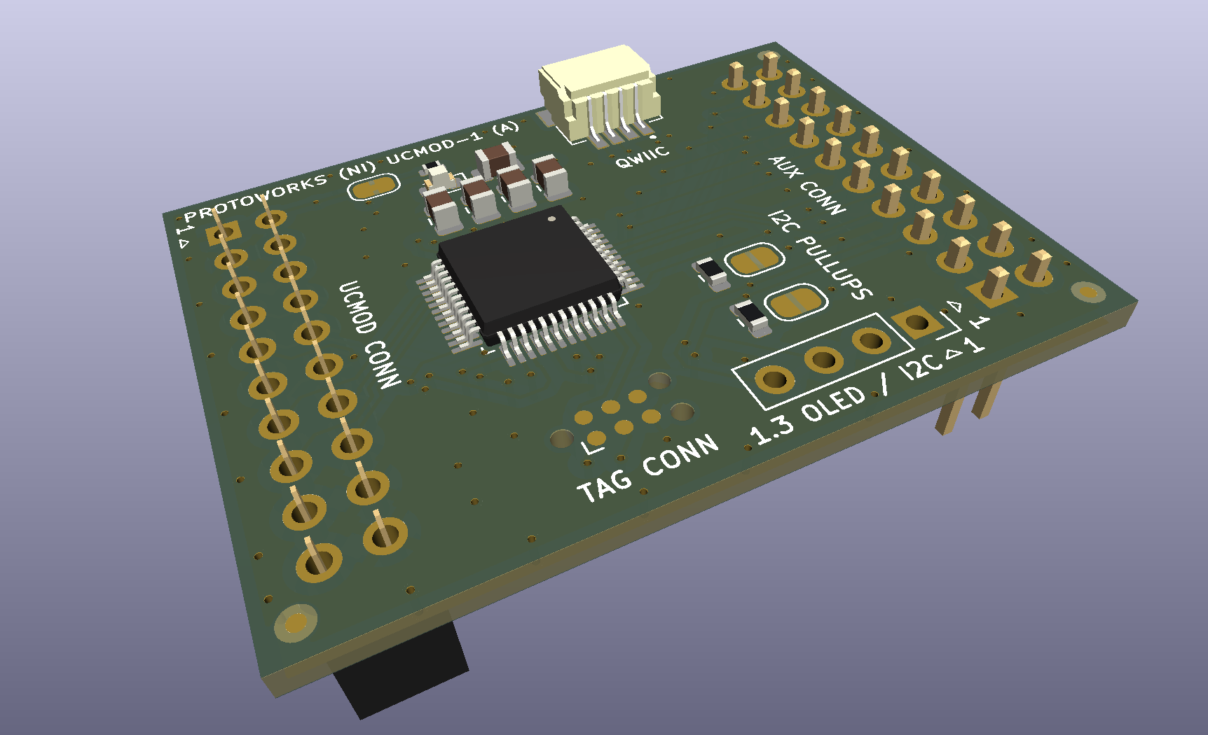
The STM32G0 UCMOD-1 KiCad Module
Small and Large UCMOD Modules#
One useful outcome of designing the STM32 board is that I think I’ve now arrived at reasonable physical formats for what I would call small and large UCMOD modules.
The distinction is fairly straightforward:
- Small UCMOD modules implement the standard UCMOD interface and prioritise compact size.
- Large UCMOD modules implement the standard UCMOD interface along with the Auxiliary UCMOD connector, providing more room and access to additional microcontroller functionality.
This gives UCMOD two useful mechanical classes without changing the basic electrical philosophy of the system.
Small UCMOD#
Small UCMOD boards will implement the basic UCMOD pinout and use a single 2×10, 2.54 mm-pitch socket header.
The target board dimensions will typically be around 30 mm wide by 25 mm deep, with the UCMOD connector centred along the 30 mm edge.
This size should fit nicely onto a carrier board while remaining compact. Mechanically, the existing boards also appear to be reasonably secure once plugged in and require a decent amount of force to remove.
Large UCMOD#
Large UCMOD boards will use both the standard UCMOD socket header and an additional 2×10 male pin header for the Auxiliary UCMOD connector.
Using a male header for the auxiliary connection, rather than another socket, gives the two connectors different mechanical genders. When paired with the corresponding carrier board, this should mechanically prevent the module from being installed the wrong way around.
The target dimensions for large modules will be approximately 30 mm wide by 40 mm deep, with the standard UCMOD connector centred on one 30 mm edge and the Auxiliary UCMOD connector centred on the opposite edge.
Mechanically, this arrangement should also be quite secure. The boards are somewhat larger, but having both connectors engaged with the carrier should provide plenty of support.
Manufacture Now, or Test the Format First?#
I’m currently undecided whether I should manufacture the STM32 boards immediately or wait until I’ve designed another large UCMOD module — perhaps an ESP32-WROOM-based board.
Designing a second module around the same 30 × 40 mm footprint would give me a better indication of whether the larger board dimensions and connector arrangement represent a genuinely reusable standard rather than simply being convenient for this particular STM32 design.
I may still get three or four of the STM32 boards made once I’ve redesigned the “Just Boards” UCMOD carrier so that it can accommodate the larger modules.
That carrier and the STM32 module should prove useful for another project I already have on the starting blocks, so it would also give me a good opportunity to start dogfooding my own modules in a real project.
At this point, that is probably one of the more useful tests I can give the UCMOD concept.
- 2026-10-17 Refining the Protoworks service offerings Lab
- 2026-09-27 Belfast Tech Week Lab
- 2026-09-19 Refining the UCMOD Architecture R&D
- 2026-09-06 Giving AI Agents a Way to Talk to Protoworks Software
- 2026-09-03 A Morning at a Manufacturing Trade Show Lab
- 2026-09-01 Debugging 921600 Baud on the ATtiny1614 R&D