RS485 Breakout with 48V Passthrough Building Block Board — Part 2
RS485 Breakout with 48V Passthrough Building Block Board — Part 2#
Today I spent some time refining the design for my RS485 building block board.
One of the more significant changes was actually the removal of a feature. I decided to remove the RJ45 connector and replace it with a second 5-position screw terminal.
I also added a second 2-position screw terminal for passing 48 V out from the board. This output is not protected by a separate fuse on the output side. Instead, the protection is intended to be handled at the 48 V input side. If 48 V is delivered through the 5-position screw terminals instead, then the upstream board or device providing that 48 V feed should provide the relevant protection.
The original idea behind using RJ45 was to make it easier to daisy-chain RS485 devices using commonly available network-style cables. In practice, though, it started to feel like it added more risk than value.
The biggest concern was accidental misuse. An RJ45 socket strongly suggests “network connection” to most people, and I did not like the idea of someone plugging the board into a laptop, switch, router, or other Ethernet device — especially with 48 V present on the board.
It also did not really simplify deployment as much as I first thought. If the board used an RJ45 connector on one side and screw terminals on the other, then anyone deploying several of these boards would need to deal with both crimped RJ45 cables and screw-terminal wiring. Instead of making the system easier to install, I was potentially making it more awkward.
By moving to screw terminals on both sides, the board becomes more explicit:
- RS485 in/out
- optional 48 V passthrough
- logic-side connections
- no confusing “this looks like Ethernet” connector
Separating the 48 V and Logic Regions#
I also spent time cleaning up the power and ground arrangement on the PCB.
The board is now laid out with two clearly defined regions: a 48 V / 48 V return region, and a logic / logic ground region. This is not galvanic isolation — the board is still a non-isolated RS485 breakout — but it does help keep the 48 V power distribution away from the low-voltage logic area.
The goal is to avoid using the logic ground as a general return path for the 48 V rail. Keeping those areas physically and electrically distinct should reduce unwanted coupling, make the current paths easier to understand, and generally make the board more predictable during testing.
I have also included an optional DNP link between 48V_RET and logic ground. By default this would not be fitted, but it gives me a controlled way to join the two references if a particular system requires it.
At this stage the board is still very much a building block rather than a finished product. The aim is to validate the RS485 transceiver circuit, the protection components, the connector arrangement, and the 48 V passthrough approach before reusing the design in larger projects.
The next step is to do another pass over the schematic, PCB layout, silkscreen, and BOM before deciding whether this revision is ready to send for manufacture.
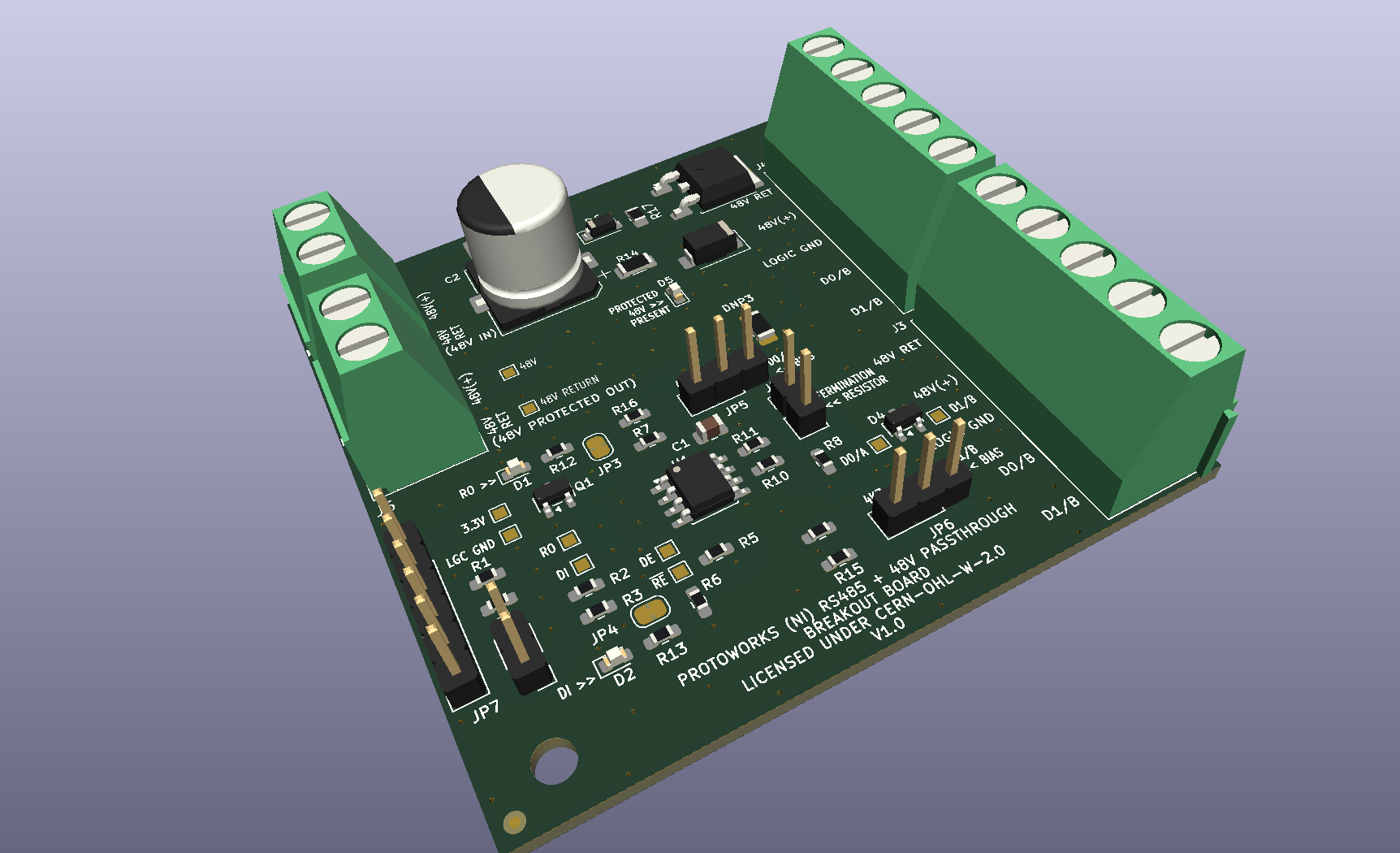
3D render of the RS485 Building Block Board
For clarity, this board is intended for controlled prototyping and internal system wiring. It is not intended for connection to Ethernet equipment or PoE networks.
Update on the 3.3 V Regulator Building Block Board#
As a small related update, I also received a notification that the 3.3 V Regulator Building Block Boards I had assembled by JLCPCB have now arrived in the UK.
Once they are in my hands, the next step will be to inspect them, power them up carefully, and start validating the design.
If you are looking for reusable open hardware modules to speed up your bench testing, or need support designing custom breakout circuits, check out our catalog at Protoworks (NI).
- 2026-10-17 Refining the Protoworks service offerings Lab
- 2026-09-27 Belfast Tech Week Lab
- 2026-09-19 Refining the UCMOD Architecture R&D
- 2026-09-06 Giving AI Agents a Way to Talk to Protoworks Software
- 2026-09-03 A Morning at a Manufacturing Trade Show Lab
- 2026-09-01 Debugging 921600 Baud on the ATtiny1614 R&D