Two Simple Boards for the Just Boards Range
Today I decided to design two simple PCBs for my ‘Just Boards’ range. Unlike most of my other boards, these are intended primarily for user assembly rather than PCB assembly services. They’re deliberately simple, use common components wherever possible, and should require little more than a decent soldering iron to assemble.
The bare PCBs can be ordered from manufacturers such as JLCPCB or PCBWay, while the components themselves are standard parts that can be sourced from Amazon or other electronics suppliers. The aim is to keep these boards inexpensive, accessible and easy to build without requiring solder paste, stencils, hot-air rework equipment or other specialist tools. In most cases, a soldering iron — and perhaps a little Blu Tack to hold components in place while the board is turned over — should be enough.
The first board is a simple adapter that creates a connection between a UPDI Friend, available from Adafruit and its distributors, and a Tag-Connect cable without the need for loose jumper wires. This makes programming ATtiny-based UCMOD boards considerably tidier and more convenient.
The UPDI Friend plugs into one end of the adapter using the three-pin 0.1-inch pitch header that can be soldered onto the UPDI Friend board. The other end of the adapter contains a six-pin shrouded IDC header that mates with a compatible Tag-Connect cable (specifically the TC2030-IDC-NL), which can then be connected directly to the programming footprint on an ATtiny-based UCMOD board.
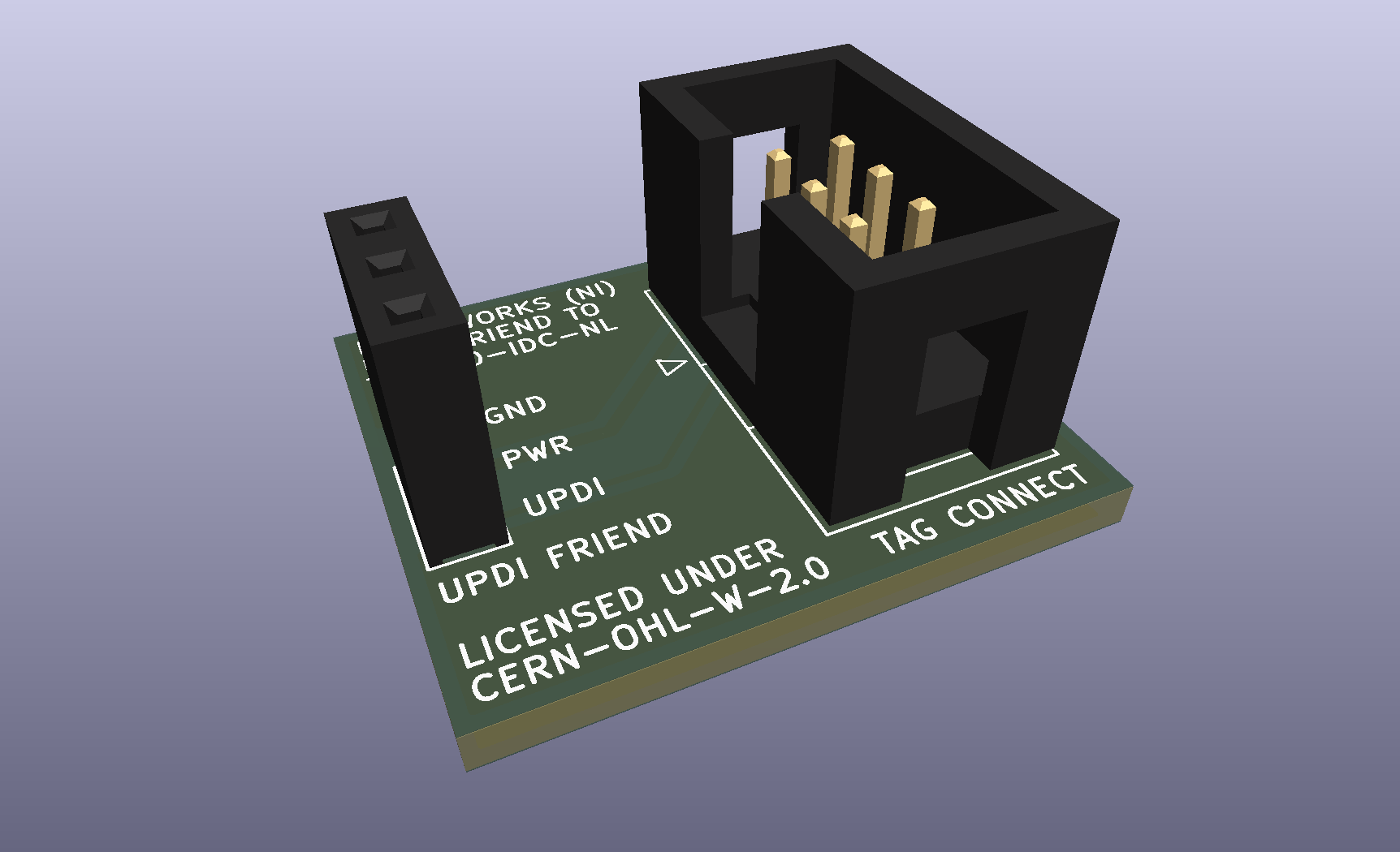
UPDI Friend to Tag-Connect Adapter Board
The second board is a simple breakout and carrier board for UCMOD-compatible microcontroller modules, such as the UCMOD-0, which is based on the ATtiny1614.
It provides an easy way to use a UCMOD module on the bench without first having to design a dedicated carrier board, making it useful for prototyping, firmware development and experimenting with peripherals.
The 2x10 UCMOD header accepts the microcontroller module, while two 1x10 0.1-inch pitch female headers on either side of the board provide easy access to the UCMOD signals. An optional footprint for a power LED and its associated current-limiting resistor is also included to indicate when 3.3V is being supplied to the board. The board also features a 1x5 0.1-inch pitch header footprint, which can be populated with a connector to accept an external 3.3V power supply, such as the USB-C Power Input & 3.3 V Regulator Board.
Beyond the LED and connectors, there is no additional circuitry. The intention is simply to provide straightforward access to the UCMOD interface in a format that can easily be used with jumper wires, breadboards and other development hardware.
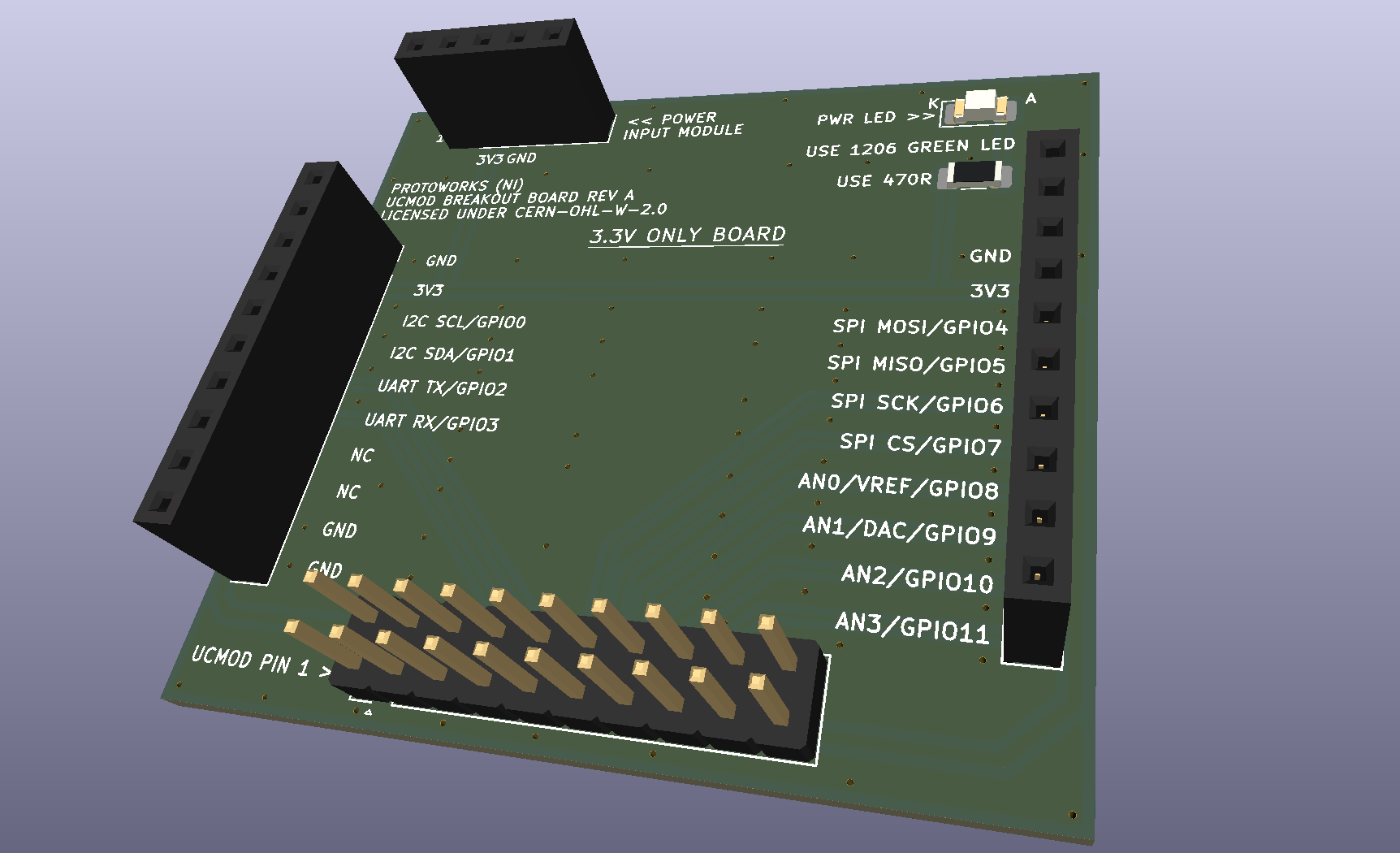
UCMOD Breakout Board showing the labelled GPIO and peripheral connections
I placed low-priority orders for both bare PCBs with PCBWay, and they should be delivered sometime within the next two or three weeks via the postal service rather than a courier. The components for the boards should be arriving around the same time.
Once everything arrives, I’ll assemble both boards, test them and see whether the deliberately simple, self-assembly approach behind the Just Boards range works as intended.
- 2026-10-17 Refining the Protoworks service offerings Lab
- 2026-09-27 Belfast Tech Week Lab
- 2026-09-19 Refining the UCMOD Architecture R&D
- 2026-09-06 Giving AI Agents a Way to Talk to Protoworks Software
- 2026-09-03 A Morning at a Manufacturing Trade Show Lab
- 2026-09-01 Debugging 921600 Baud on the ATtiny1614 R&D